ECG Recording
ECG Recording
Understanding ECGs, also known as Electrocardiograms, aids in the diagnosis and treatment of a wide array of cardiac conditions. Yet, if ECG recordings are not conducted or recorded correctly it could lead to misinterpretation, potentially incorrectly diagnosing life-threatening conditions such as an STEMI (ST Elevation Myocardial Infarction)
Equipment, electrode placement, artifact and a plethora of other human factors could produce an incorrect ECG recording.
ECG Machine
The equipment used for an ECG recording is highly sensitive and incorrect setup of this equipment could cause misinterpretation.
Most modern ECG recording machines offer tools that help assist the clinician to interpret rhythms along with customisation of changing recording settings to suit specific clinicals needs (e.g. changing recording from rhythms strips to 12-lead in real time).
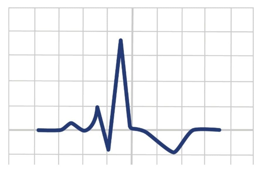
ECG Paper
ECGs (made up of many vertical and horizontal lines), to a new learner, can be daunting for the first time. Horizontal lines on the ECG recording paper records the duration whereas vertical lines record the amplitude.
Horizontal Lines
Standard speed for ECG recordings is 25 mm/s which makes it easier to measure time intervals and calculate heart rate accurately. It also ensures consistency in comparing ECGs across different settings and over time.
When set at 25 mm/s, each smaller square on the paper represents 0.04 seconds (40 milliseconds). Each large square of the paper accommodates 5 small squares which make a large square represent 0.2s (200ms)
Before recording ECGs is it important to check the speed setting. However, some cases may warrant different speed settings to allow for a more detailed analysis of specific segments (e.g. 100mm/s for exercise stress testing).
Vertical Lines
Amplitude, represented on the vertical axis, can be used to measure the height of the ECG waveforms accurately.
Standard amplitude calibration for most ECGs is 1 millivolt (mV). This allowed an amplitude of 1mV to show a deflection of 10mm (10mm/mV)
Many ECG machines have a “gain” or “calibration” control that allows users to adjust the amplitude setting. By changing the gain control, the amplitude of the ECG waveforms can be increased or decreased. A higher gain setting makes the waveforms appear larger on the ECG, while a lower gain setting makes them appear smaller. Gain control can be used to enhance the visualisation of specific components of the ECG recording, such as P-waves or QRS complexes.

Artifact
Artifacts in ECG recordings refer to unwanted interference or disturbances in the ECG waveform that are not representative of the heart’s electrical activity.
Muscle Artifacts
Muscle artifacts result from the contraction of skeletal muscles near the electrodes. These artifacts typically appear as low-frequency, irregular waves or spikes on the ECG. They can be caused by patient movement, shivering, or tremors.
Electrode Displacement
Electrode displacement occurs when one or more ECG electrodes become partially or completely detached from the skin or shift during the recording. This can lead to irregular waveforms, baseline wander, or electrode noise.
Lead Wire Noise
Lead wire noise is caused by damaged or poorly shielded ECG cables or wires. It can introduce high-frequency interference, such as sharp spikes or irregularities, into the ECG recording.
Electrical Interference
Electrical interference from power lines and electrical equipment can result in a regular, sinusoidal waveform on the ECG. This interference is often referred to as “AC interference” and can affect ECG quality, especially when poor grounding or electrical shielding is present.
Respiratory Artifacts
Respiratory artifacts occur due to variations in chest movement during respiration. These artifacts manifest as rhythmic disturbances in the ECG, often seen as baseline fluctuations.
Baseline Wander
Baseline wander refers to slow, low-frequency fluctuations in the baseline of the ECG. It can be caused by various factors, including poor skin-electrode contact, electrode drying, and electrode movement. Baseline wander can make it challenging to discern small ECG abnormalities.
Electronic Devices
Electronic devices, fluorescent lights, and other electromagnetic sources in the vicinity of the ECG machine can introduce interference into the ECG recording. This interference may appear as irregular waveforms or noise.
Lead Reversal
Incorrect lead placement can lead to lead reversal artifacts, where ECG leads are connected in the wrong order or to the wrong electrodes. This can result in inverted or abnormal waveforms.
Limb Lead Placement
Limb leads record electrical activity between two electrodes placed on the patient’s limbs. There are three bipolar limb leads (I, II, and III) and three augmented unipolar limb leads (aVR, aVL, and aVF). See more about electrical views here.
Limb leads are labelled as R (Right), L (Left), F (Foot), N (Neutral). These cables are also colour coded Red, Yellow, Green and Black respectively.
Lead R (Red) is placed on the right inner wrist.
Lead L (Yellow) is placed on the left inner wrist.
Lead F (Green) is placed on the left leg
Lead N (Black) is placed on the right leg
A well know mnemonic Ride, Your, Green, Bike can be used to help remember the limb lead placement.
Whilst on the road there may be difference on opinion on limb placement. Gold standard placement involves placing limb leads on distal arms and legs near wrist and ankles not torso or chest.

Precordial Leads (Chest Leads) Placement
Precordial leads record electrical activity from various angles in the frontal plane. There are six standard precordial leads (V1, V2, V3, V4, V5, and V6).
V1: Fourth intercostal space on the right of the sternal edge
V2: Fourth intercostal space on the left of the sternal edge
V3: Midway between V2 and V4, following the intercostal spaces.
V4: Fifth intercostal space, at the mid-clavicular line.
V5: Anterior axillary line, in the same horizontal plane as V4.
V6: Mid-axillary line, aligned with V4 and V5.
Finding the correct intercostal space should be carried out by using the sternal notch. The sternal notch is classed as the first intercostal space.
Correct ECG electrode placement is crucial for accurate cardiac interpretation and diagnoses. It ensures that the electrical signals of the heart are recorded consistently and can be interpreted effectively by clinicians.

Conclusion
ECGs are a fundamental procedure in healthcare, providing invaluable insights into the heart’s electrical activity. Proper electrode placement, calibration, and standardisation are essential for accurate and reliable ECG recordings. ECGs are critical for diagnosing a wide range of cardiac conditions and play a central role in patient care.
Key Points
- Correct placement of limb and precordial leads is important to obtain an accurate ECG
- Standard speed for ECG recordings is 25 mm/s and the standard amplitude is 1mV
- There are many unwanted interference or disturbances that may cause artifacts in ECGs.
Bibliography
Joint Royal Colleges Ambulance Liaison Committee and Association of Ambulance Chief Executives (2022). JRCALC Clinical Guidelines 2022. Class Professional Publishing
Tung, R. T. (2021). Electrocardiographic Limb Leads Placement and Its Clinical Implication: Two Cases of Electrocardiographic Illustrations. Kansas Journal of Medicine, 14, 229–230. https://doi.org/10.17161/kjm.vol1415259
ECG Recording
Understanding ECGs, also known as Electrocardiograms, aids in the diagnosis and treatment of a wide array of cardiac conditions. Yet, if ECGs are not conducted or recorded correctly it could lead to misinterpretation, potentially incorrectly diagnosing life-threatening conditions such as an STEMI (ST Elevation Myocardial Infarction)
Equipment, electrode placement, artifact and a plethora of other human factors could produce an incorrect ECG recording.
ECG Machine
The equipment used to record an ECG is highly sensitive and incorrect setup of this equipment could cause misinterpretation.
Most modern ECG machines offer tools that help assist the clinician to interpret rhythms along with customisation of changing recording settings to suit specific clinicals needs (e.g. changing recording from rhythms strips to 12-lead in real time).
ECG Paper
ECGs (made up of many vertical and horizontal lines), to a new learner, can be daunting for the first time. Horizontal lines on the ECG paper record the duration whereas vertical lines record the amplitude.
Horizontal Lines
Standard speed for ECG recordings is 25 mm/s which makes it easier to measure time intervals and calculate heart rate accurately. It also ensures consistency in comparing ECGs across different settings and over time.
When set at 25 mm/s, each smaller square on the paper represents 0.04 seconds (40 milliseconds). Each large square of the paper accommodates 5 small squares which make a large square represent 0.2s (200ms)
Before recording ECGs is it important to check the speed setting. However, some cases may warrant different speed settings to allow for a more detailed analysis of specific segments (e.g. 100mm/s for exercise stress testing).
Vertical Lines
Amplitude, represented on the vertical axis, can be used to measure the height of the ECG waveforms accurately.
Standard amplitude calibration for most ECGs is 1 millivolt (mV). This allowed an amplitude of 1mV to show a deflection of 10mm (10mm/mV)
Many ECG machines have a “gain” or “calibration” control that allows users to adjust the amplitude setting. By changing the gain control, the amplitude of the ECG waveforms can be increased or decreased. A higher gain setting makes the waveforms appear larger on the ECG, while a lower gain setting makes them appear smaller. Gain control can be used to enhance the visualization of specific components of the ECG, such as P-waves or QRS complexes.
Artifact
Artifacts in ECGs (Electrocardiograms) refer to unwanted interference or disturbances in the ECG waveform that are not representative of the heart’s electrical activity.
Muscle Artifacts
Muscle artifacts result from the contraction of skeletal muscles near the electrodes. These artifacts typically appear as low-frequency, irregular waves or spikes on the ECG. They can be caused by patient movement, shivering, or tremors.
Lead Reversal
Incorrect lead placement can lead to lead reversal artifacts, where ECG leads are connected in the wrong order or to the wrong electrodes. This can result in inverted or abnormal waveforms.
Electronic Devices
Electronic devices, fluorescent lights, and other electromagnetic sources in the vicinity of the ECG machine can introduce interference into the ECG recording. This interference may appear as irregular waveforms or noise.
Baseline Wander
Baseline wander refers to slow, low-frequency fluctuations in the baseline of the ECG. It can be caused by various factors, including poor skin-electrode contact, electrode drying, and electrode movement. Baseline wander can make it challenging to discern small ECG abnormalities.
Respiratory Artifacts
Respiratory artifacts occur due to variations in chest movement during respiration. These artifacts manifest as rhythmic disturbances in the ECG, often seen as baseline fluctuations.
Electrical Interference
Electrical interference from power lines and electrical equipment can result in a regular, sinusoidal waveform on the ECG. This interference is often referred to as “AC interference” and can affect ECG quality, especially when poor grounding or electrical shielding is present.
Lead Wire Noise
Lead wire noise is caused by damaged or poorly shielded ECG cables or wires. It can introduce high-frequency interference, such as sharp spikes or irregularities, into the ECG recording.
Electrode Displacement
Electrode displacement occurs when one or more ECG electrodes become partially or completely detached from the skin or shift during the recording. This can lead to irregular waveforms, baseline wander, or electrode noise.
Limb Lead Placement
Limb leads record electrical activity between two electrodes placed on the patient’s limbs. There are three bipolar limb leads (I, II, and III) and three augmented unipolar limb leads (aVR, aVL, and aVF). See more about electrical views here.
Limb leads are labelled as R (Right), L (Left), F (Foot), N (Neutral). These cables are also colour coded Red, Yellow, Green and Black respectively.
Lead R (Red) is placed on the right inner wrist.
Lead L (Yellow) is placed on the left inner wrist.
Lead F (Green) is placed on the left leg
Lead N (Black) is placed on the right leg
A well know mnemonic Ride, Your, Green, Bike can be used to help remember the limb lead placement.
Whilst on the road there may be difference on opinion on limb placement. Gold standard placement involves placing limb leads on distal arms and legs near wrist and ankles not torso or chest.
Precordial Leads (Chest Leads)
Precordial leads record electrical activity from various angles in the frontal plane. There are six standard precordial leads (V1, V2, V3, V4, V5, and V6).
V1: Fourth intercostal space on the right of the sternal edge
V2: Fourth intercostal space on the left of the sternal edge
V3: Midway between V2 and V4, following the intercostal spaces.
V4: Fifth intercostal space, at the mid-clavicular line.
V5: Anterior axillary line, in the same horizontal plane as V4.
V6: Mid-axillary line, aligned with V4 and V5.
Finding the correct intercostal space should be carried out by using the sternal notch. The sternal notch is classed as the first intercostal space.
Correct ECG electrode placement is crucial for accurate cardiac interpretation and diagnoses. It ensures that the electrical signals of the heart are recorded consistently and can be interpreted effectively by clinicians.
Conclusion
ECGs are a fundamental procedure in healthcare, providing invaluable insights into the heart’s electrical activity. Proper electrode placement, calibration, and standardisation are essential for accurate and reliable recordings. ECGs are critical for diagnosing a wide range of cardiac conditions and play a central role in patient care.
Key Points
- Correct placement of limb and precordial leads is important to obtain an accurate ECG
- Standard speed for ECG recordings is 25 mm/s and the standard amplitude is 1mV
- There are many unwanted interference or disturbances that may cause artifacts in ECGs.
Bibliography
Joint Royal Colleges Ambulance Liaison Committee and Association of Ambulance Chief Executives (2022). JRCALC Clinical Guidelines 2022. Class Professional Publishing
Tung, R. T. (2021). Electrocardiographic Limb Leads Placement and Its Clinical Implication: Two Cases of Electrocardiographic Illustrations. Kansas Journal of Medicine, 14, 229–230. https://doi.org/10.17161/kjm.vol1415259